Projets:Motorized head support
Project overview
To manufacture a low-cost assistive device to support and allow the rotation of the head of a person whose muscular deficiency in the neck area does not allow them neither a natural support of their head nor a natural rotation from left to right (rotation of the head is impossible muscularly, only articularly). Mathilde does not wish to get yet another remote control button to make use of this functionality because she already has several of them and she cannot always access them depending on the situation.
Design brief
Existing prototype(s) analysis
Team (Project leader and contributors)
- Project leader(s) :
Mathilde Fuchs
- Designers/Contributors :
Philippe Pacotte, Stéphane Godin, André Bécot, Jean-Pierre Legrand, Yves Le Chevalier, Christian Fromentin, Danke, Francis Esnault, Jean-François Duguest, Brice Besançon, Yohann Véron,
- Animator (Project coordinator)
Delphine Bézier
- Referent fabmanager
Delphine Bézier
- Documentation manager
Required components
| # | Component | Quantity | Price |
|---|---|---|---|
| 1 | Arduino-NANO | 1 | ? |
| 2 | resistor-1K | 4 | ? |
| 3 | micro-switch | 4 | ? |
| 4 | nema17-42SHD0228 | 1 | ? |
| 5 | veroboard | 1 | ? |
| 6 | battery-12V | 2 | ? |
| 7 | big-easy-driver card | 1 | ? |
| 8 | branch circuit box | 1 | ? |
| 9 | pulley-GT2-bore5-20toothed | 1 | ? |
| 10 | nema17 | 1 | ? |
| 11 | screw-M3-12 | 2 | ? |
| 12 | bearing-F624ZZ | 4 | ? |
| 13 | end plate | 4 | ? |
| 14 | monofilament wiring-0.2 | 1 | ? |
| 15 | screw CHc-M2X16 | 2 | ? |
| 16 | nut-M2 | 2 | ? |
| 17 | screw CHc-M3x14 | 2 | ? |
| 18 | nuts-nylstop-M3 | 4 | ? |
| 19 | screw-CHc-M5X35 | 1 | ? |
| 20 | nut-nylstop | 1 | ? |
| 21 | screw-CHc-M5X15 | 1 | ? |
| 22 | end plate | 1 | ? |
| 23 | screw-M3 | 2 | ? |
Required tools
Cost
Estimated timeframe
Source files
Step by step manufacturing process
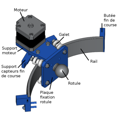
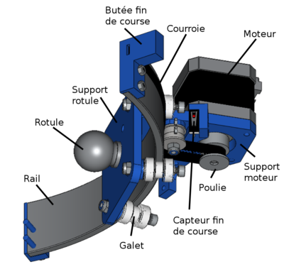
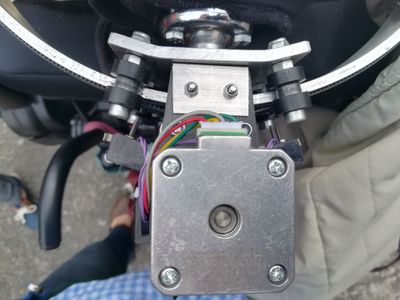
Step 1 - Captioned view of the final prototype
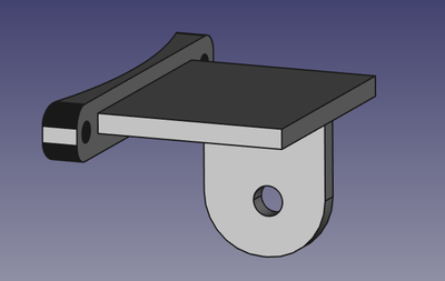
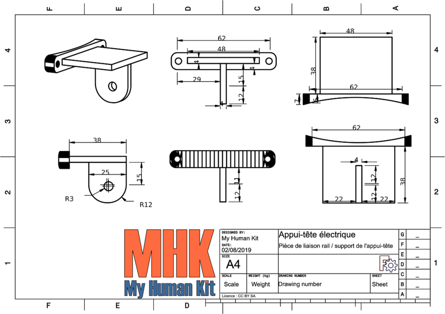
Step 2 - Fabrication of the connecting piece between the rail and the adjustable support of the chair head restraint
The connecting piece between the rail and the adjustable support of the head restraint attached to the chair was made from three flat bars welded together. Refer to the file "support entre rail et fauteuil.stl".
Download the stl file support between rail and chair
Step 3 - Rail fabrication
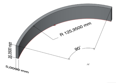
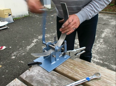
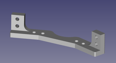
To manufacture the rail, take the 4G aluminum plate (see picture for dimensions) and adjust the curvature of the bending machine as seen on STL file. It might be possible to make a cardboard or 3D printed installation template to check and adjust the curve. Watch how to proceed here :
Then drill the holes and filter them for the end stop switches, the position of which is to be adjusted according to the desired degree of movement or the head rotation, which must remain comfortable for the user.
Step 4 - Fabrication of the mounting ball
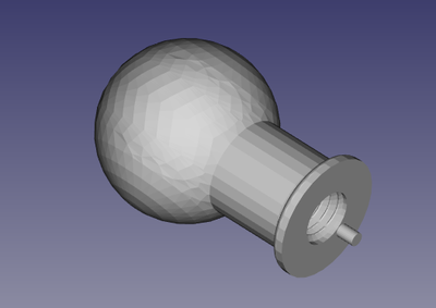
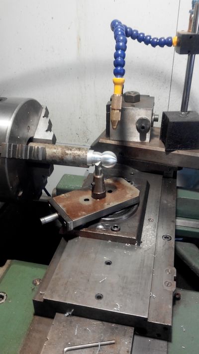
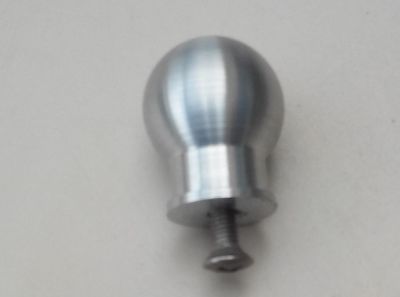
Depending on the person's head restraint, the dimensions of the mounting ball will need to be adjusted. If the model corresponds to this one, ask a machinist to manufacture it out of 4G aluminium according to the STL model (rotule.stl). It will then be necessary to drill and filter it (for a CHc-M5X15 screw) to attach it. Caution : add a steel locking pin to the baseplate of the ball joint parallel to the screw which also goes on the on the mounting ball support to avoid the rotation of the ball on itself.
Step 5 - Fabrication of the ball mounting plate and rollers
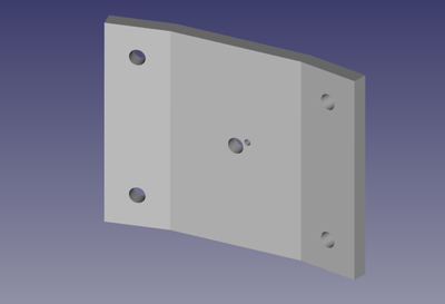
Manufacture the ball mounting plate with a folding machine based on the plaquerotule.stl file.
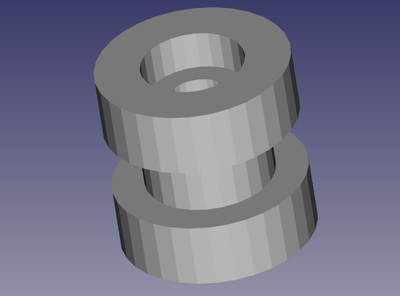
Manufacture the four rollers (5mm sheave rollers inside groove width and 2.5mm shoulder sheave) Machine the four rollers in POM-C plastic material (Nylacast Polyacetal POM-C otherwise known as Acetal Copolymer is an engineered plastic) with an outer diameter of 15mm and inner diameter of 10mm. Bore them for the rollers that attach at the two extremities.
File:galet_perce.stl File:plaquerotule.stl
Step 6 - 3D printing of the components (simulate printing time in Cura)
Print every component located in the " STL/A print " folder.
- Filament material: preferably ABS or PLA
- Cura configuration settings : Density: 90 % filling, quality 0.2.
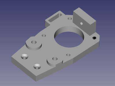
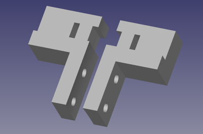
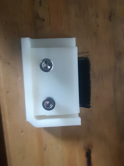
Printout of end stops, motor mount, limit switch sensor lug as well as the protective cover.
File:support_capteurs_fin_course.stl
Step 7 - Fabrication of the electronic circuit
Required components:
- Arduino-NANO
- resistor-1K
- micro-switch
- nema17-42SHD0228
- veroboard
- battery-12V
- big-easy-driver card
___________________________________
- PCB (to which the on/off circuit must be added)
- Arduino file (code)
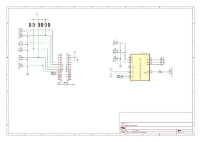
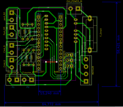
Manufacture or have the printed circuit board made by referring to the schematic and PCB below (Headrestschemav1.2.jpg, headrests-PCBv1.2.png).
Upload the code to the Arduino board.
#include "cli.h"
#include "config.h"


#include "command.h"


// task definition for periodic scheduling 1ms
//void motorControl(Task* me);
//Task schedule (1, motorControl);


void setup() {

  // intialize command
  cli_open ();

  // initialize motor
  load_config ();
  get_stepper()->setMaxSpeed (get_speed());
  get_stepper()->setAcceleration (get_accel());
  // initialize led
  pinMode(LED, OUTPUT);
  digitalWrite (LED, LOW);

  // initialize buttons
  pinMode(BTN_RIGHT, INPUT);
  pinMode(BTN_LEFT, INPUT);

  // stepper microstep
  pinMode (MOTOR_MS1, OUTPUT),
  pinMode (MOTOR_MS2, OUTPUT);
  digitalWrite (MOTOR_MS1, LOW); // todo place config in config.h
  digitalWrite (MOTOR_MS2, LOW);

  //endstop
  pinMode (ENDSTOP_LEFT, INPUT),
  pinMode (ENDSTOP_RIGHT, INPUT);


  // run scheduler
  //SoftTimer.add(&schedule);

}

// function :SensorLeft
//
// Description :
// return te logic state of the left sensor
//
// Return :
// true if the left sensor is active. Otherwise false
boolean SensorLeft ()
{
  if (get_force_left () > 0)
    return (true);
  return (digitalRead (BTN_LEFT)== BTN_LEFT_ACTIVE_STATE ? true : false);
}

// function :SensorRight
//
// Description :
// return te logic state of the right sensor
//
// Return :
// true if the right sensor is active. Otherwise false
boolean SensorRight()
{
  if (get_force_right () > 0)
    return (true);
  return (digitalRead (BTN_RIGHT) == BTN_RIGHT_ACTIVE_STATE ? true : false);
}

// function :EndStopLeft
//
// Description :
// return the logic state of the left endstop sensor
//
// Return :
// true if the left endstop is active. Otherwise false
boolean EndStopLeft ()
{
  return (digitalRead (ENDSTOP_LEFT) == ENDSTOP_LEFT_STATE ? true : false);
}

// function :EndStopRight
//
// Description :
// return the logic state of the right endstop sensor
//
// Return :
// true if the right endstop is active. Otherwise false
boolean EndStopRight ()
{
  return (digitalRead (ENDSTOP_RIGHT) == ENDSTOP_RIGHT_STATE ?  true : false);
}

int RIGHT_MOVE = 1;
int LEFT_MOVE = -1;
int STOP_MOVE = 0;

//void turnOn(Task* me)
//{

//}


// Function: motorControl
//
// Description :
// The function is called every 1 ms. check command sensor and enstop and control the motor
//
//
//void motorControl(Task* me)
void loop ()
{
  AccelStepper *pstepper = get_stepper ();

  // put your main code here, to run repeatedly:

  int step = 0;
  // decide move
  int move = STOP_MOVE;

  boolean right = SensorRight ();
  boolean left = SensorLeft ();

  boolean endl = EndStopLeft ();
  boolean endr = EndStopRight ();


 if (endr || endl)
  digitalWrite (LED, HIGH);
  else
  digitalWrite (LED,LOW);

 //endr = false;
 //endl=false;
  if (right == left)
  {
    move = STOP_MOVE;

    //digitalWrite(LED, LOW);
  }
  else if (right==true)
  {
    if (endr)
    {
      move=STOP_MOVE;
    }
    else
    {
      move = RIGHT_MOVE;
      pstepper->move (20000);
      //digitalWrite(LED, HIGH);
    }
  }
  else if (left == true)
  {
    if (endl)
    {
      move=STOP_MOVE;
    }
    else
    {
      move = LEFT_MOVE;
      pstepper->move(-20000);
      //digitalWrite(LED, HIGH);
    }
  }

  // motor control
  if (move != STOP_MOVE)
  {
    pstepper->run();
  }
  else
  {
    //stepper1.disableOutputs();
    pstepper->setSpeed(0);
    pstepper->setCurrentPosition (0);
  }

  // process command
   CLI.process();
}
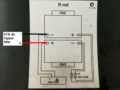
The arduino card is powered with 5V from the 5V output of the easy driver card. Connect the 24V from the PCB to the chair batteries (see Schema_batterie.jpg).
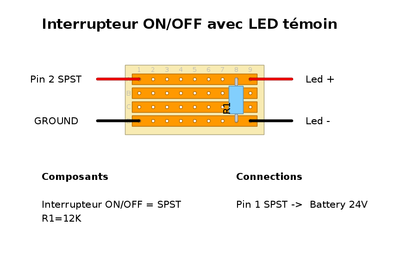
Add the LED ON/OFF switch circuit (presented on the provided picture) to be able to switch off the device and not use battery power for nothing. :)
Step 8 - Installation of the circuit in the electronic circuit box
Required component:
- electrical junction box
Place the circuit in the waterproof electrical junction box. Waterproof electrical junction box reference: https://www.leroymerlin.fr/v3/p/produits/boite-de-derivation-etanche-en-saillie-debflex-8-entrees-e29160
The box will be mounted to the rear of the chair.
Step 9 - Assembly of the button or system, chosen to control the rotary head restraint
Assemble the button according to the following diagram. Prepare the cable length in advance to connect the cable to the PCB located in the housing that has been mounted to the rear of the chair.
Step 10 - Mounting of the GT2 bore 5 pulley to the NEMA17 stepper motor
Required components:
- pulley-GT2-bore5-20toothed
- nema17
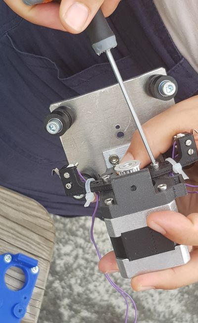
Thread the GT2 bore 5 20toothed pulley on the shaft of the Nema17 motor. Then attach it with two screws with no locking head of the pulley.
Refer to the picture of the global diagram.
Step 11 - Attaching the motor + pulley, to the motor support
Required component:
- screw-M3-12
Attach the set motor + pulley on the motor support using two M3x12 screws.
Étape 12 - Mounting the bearings to run the strap
Required components:
- bearings-F624ZZ
- rings
Attach the four ball bearings F624ZZ placed in mirror pairs with the outer pointed shoulder, with the rings placed between the screw and the bearing, to avoid compressing the outer part of the bearing. And on the other side of the motor support plate, place the M4x20 (or 25) screw with a nylstop nut.
Step 13 - Wiring of the end-stop switch sensors
Required components:
- micro-switch
- monofilament-0.2
Weld the wires to the end-stop switches (also called microswitches). Prepare sufficient wire length to reach the housing where the electronic circuit is located.
Step 14 - Mounting end stop switches on their support
Required components:
- screw CHc-M2X16
- M2 nuts
Assemble the end stop switches (microswitches) to their supports with 2 screws CHc-M2X16 each and their respective nut.
Step 15 - Installation of the end stop switches support on the motor support
Required components:
- screw CHc-M3x14
- nylstop nut M3
Attach the end stop switch sensor brackets to the motor support with 2 screws CHc-M3x14 which are mounted to the Nema 17.
Step 16 - Preparation of the rollers
Insert an MR84ZZ bearing on both sides of each roller. Forcibly insert the bearings (two per roller) in the rollers.
Step 17 - Installation of the rollers on the baseplate of the mounting ball
Required components:
- screw-CHc-M5X35
- nylstop nut
Attach the rollers on the baseplate of the mounting ball with the CHc-M4X35 screws and M4 nylstop nuts. Do not tighten the screws all the way and leave some looseness for the installation on the rail.
Étape 18 - Assemblage de la rotule sur la plaque support rotule
Composants nécessaires:
- vis-CHc-M5X15
- rondelle
Assembler la rotule et son ergo sur la plaque avec la vis CHc-M5X15 et sa rondelle (il faut penser à mettre du frein filet si ça se déserre trop souvent).
Étape 19 - Assemblage de plaque rotule sur le rail de guidage (add photo+vis ref)
Enfiler la plaque rotule sur le rail de guidage.
Serrer les écrous de fixation des galets en ne les serrant pas trop fort pour que le coulissement soit correct.
Étape 20 - Fixation de la cornière aluminium sur la plaque de support rotule
Composants nécessaires:
- vis-M3
- ecrous-nylstop-M3
Fixer la cornière aluminium sur la plaque de support rotule. La corniere de 20x20 sur 31 mm de longueur + 2 vis M3 avec écrous nylstop + 2 vis (ref+longueur???)
Étape 21 - Pose, tension et fixation de la courroie
Pose, tension et fixation de la courroie GT2 de largeur 6 mm, pas de 2 mm et longueur environ 35mm ou ajuster la longueur selon la course du rail. La fixer à chaque extrémité en la faisant passer par le trou prévu sur la butée de fin de course, et la fixer avec un cerflex sur le côté extérieur. Les crans de la courroie doivent être orientés vers le rail.
Fixation de l'appui-tête : https://urlz.fr/bjPY
Fixation courroie : https://youtu.be/NXCGfeGCh6I
